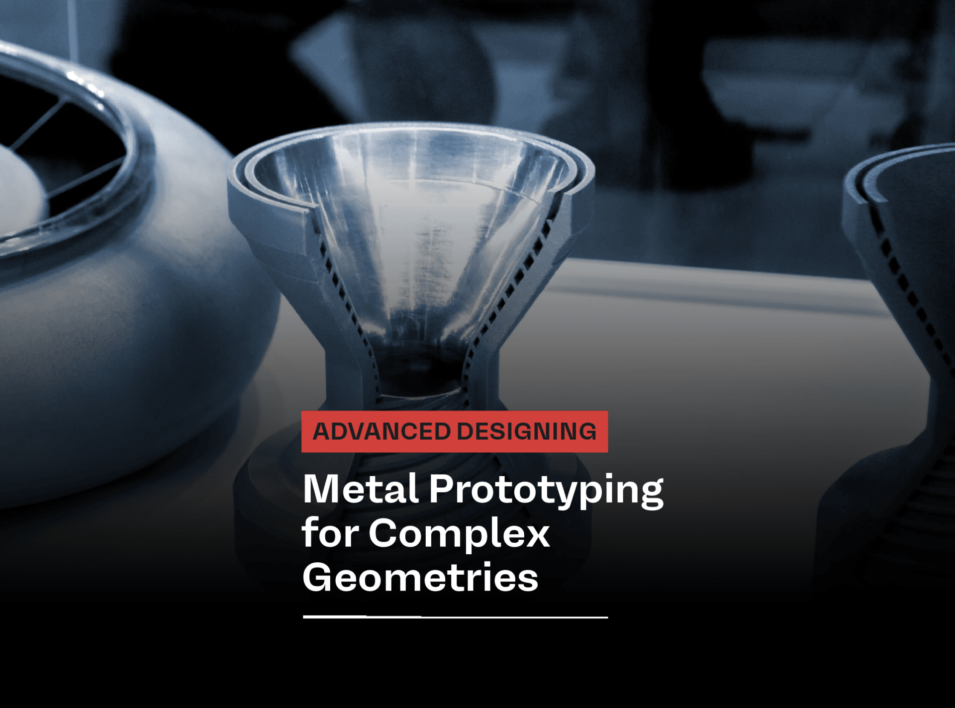
Designing advanced parts is rarely limited by CAD. In many cases, the real barrier appears later, when the team tries to manufacture the first functional prototype. This is especially true for metal prototyping projects that involve internal channels, lattice structures, thin walls, undercuts, conformal features, or shapes that require multiple operations just to become machinable.
Traditional manufacturing methods still play a major role in product development. CNC machining remains an excellent option for many metal components because it offers accuracy, repeatability, and strong surface quality. But when geometry becomes too complex, metal prototype machining can quickly turn into a compromise between what engineers want and what tools can actually produce.
That is where additive methods start to make sense. In the right application, metal additive manufacturing can reduce geometric constraints, shorten iteration loops, and help teams validate parts that are much closer to the final design intent.
What is metal prototyping and why does geometry matter?
At its core, metal prototyping means producing a physical metal part from a digital model so engineers can evaluate fit, function, manufacturability, thermal behavior, or mechanical performance before moving to full production. It is not just about creating a sample. It is about learning quickly and reducing development risk.
For simple brackets, housings, or turned parts, the path is usually straightforward. But the equation changes when the design includes:
- enclosed internal passages
- topology-optimized shapes
- lightweight lattice zones
- organic load-bearing geometries
- integrated functions in one part
- extreme aspect ratios or fine features
- material-saving hollow structures
These features are increasingly common in aerospace, energy, R&D, medical, thermal management, and advanced tooling applications. They are also exactly the kind of features that expose the limits of subtractive manufacturing during the prototype phase.
Why traditional metal prototype machining struggles with complex geometries
CNC machining is precise, but it is still constrained by tool access, fixturing, cutting strategy, and the physical logic of removing material from a solid block. That means some geometries are not impossible in theory, but become slow, expensive, or highly impractical in reality.
1. Tool access becomes the first design bottleneck
If a cutting tool cannot reach a feature, the feature usually has to be redesigned. Deep cavities, hidden channels, undercuts, or curved enclosed paths often require splitting the part into multiple components or abandoning the original geometry altogether.
This is a crucial issue in metal prototypes because the prototype should validate the real design, not a simplified workaround. If the prototype geometry is changed just to make machining possible, the engineering team may be testing the wrong part.
2. Part consolidation is difficult
Many advanced designs work best when multiple features are combined into one body. Traditional machining often pushes engineers in the opposite direction, toward separate components, secondary joining, and more assembly steps.
That adds:
- more tolerance stack-up
- more leak paths
- more weight
- more assembly time
- more failure points
For functional prototypes, this can distort the evaluation of performance, especially in fluid, thermal, or vibration-sensitive systems.
3. Cost rises sharply with complexity
Machining cost is not determined only by material and part size. It also depends on setup count, programming time, tool wear, feature accessibility, and scrap risk. A part with demanding geometry may require five-axis machining, custom fixturing, multiple reorientations, EDM support, or manual finishing.
At that point, the prototype can become too expensive for true iteration. Teams stop testing multiple options not because the design is finished, but because the prototype budget is exhausted.
4. Internal features remain a major limitation
One of the clearest dividing lines between subtractive and additive methods is the treatment of internal geometry. Machining is excellent for open, reachable features. It is fundamentally weaker when the design depends on internal flow channels, hidden heat exchangers, lightweight cores, or internal reinforcement patterns.
These are not exotic edge cases anymore. They are increasingly central to high-performance product design.
Where metal additive manufacturing succeeds
Additive manufacturing allows for on-demand production, reducing the need for large inventories and minimizing storage costs. This means manufacturers can produce parts only when they are needed, reducing waste associated with overproduction.
With on-demand manufacturing, companies can streamline their supply chains, produce parts closer to their final destination, and reduce waste throughout the production process.
Design freedom
Instead of removing material from a billet, AM builds the part layer by layer. That makes it much easier to produce:
- internal channels
- lattice structures
- conformal cooling paths
- topology-optimized parts
- thin-wall features
- integrated manifolds
- complex geometries with fewer assemblies
Recent advances in computational design have shown that a rocket engine model can now be developed algorithmically on the basis of engineering constraints, transformed into highly complex manufacturable geometry, and tested on a much shorter development cycle than would be typical with conventional methods. This is especially important in the case of aerospike engines, whose design often involves internal passages and integrated features that are extremely difficult to produce through traditional machining. Here, metal additive manufacturing enables not only faster prototyping, but also the practical testing of engine concepts that have historically been limited by manufacturing complexity.
This is why rapid prototyping metal parts with AM is so attractive in early engineering stages. Engineers can test a shape that is much closer to the performance-driven CAD model.
Faster iteration on difficult parts
For geometrically simple components, machining may still be faster. But for parts that would require multiple setups or major redesign to be machinable, additive manufacturing can compress the development loop.
Instead of asking, “How do we machine this?”, teams can ask, “Is this the right geometry for the application?” That is a much better prototyping question. The real value of https://www.amazemet.com/rapid-prototyping-innovative-product-development/ is not speed alone. It is the ability to learn earlier, with fewer design distortions.
Better alignment between prototype and final performance intent
In advanced development programs, a prototype is not only a visual sample. It may need to support:
- thermal tests
- flow tests
- mechanical screening
- assembly validation
- weight optimization studies
- material behavior comparison
When geometry is central to performance, AM can produce a more meaningful prototype than a heavily simplified machined equivalent.
Metal prototyping methods are not interchangeable
A common mistake is to treat all prototyping methods as direct substitutes. In practice, the correct route depends on what exactly must be validated.
Use machining when:
- geometry is relatively open and accessible
- tight tolerances are the main priority
- the part is prismatic or rotationally simple
- surface finish matters more than internal complexity
you need quick validation of straightforward metal features
Use additive manufacturing when:
- geometry is the main innovation
- internal features matter
- part consolidation is valuable
- redesigning for machinability would distort the test
- lightweighting is important
several iterations are expected on a complex design
Use hybrid workflows when:
- you need AM for the core geometry
- selected surfaces require finish machining
- threads, interfaces, or sealing zones need secondary operations
- the prototype must balance speed, function, and final tolerance
In other words, prototyping materials and process choice must follow the engineering objective, not just habit. The best prototyping material is the one that helps you answer the most important technical question with the least distortion and delay.
What about sheet metal, casting, and other routes?
It is worth being precise here. Not every complex metal part should be printed. Sheet metal prototyping remains an excellent method for enclosures, brackets, guards, and formed structures, particularly when the final product will also be made from sheet. It offers fast turnaround, good repeatability, and cost advantages for suitable geometries.
Likewise, casting, MIM, or conventional fabrication may be more appropriate for certain shapes, materials, or production economics. We want to say this clearly: additive manufacturing is powerful, but it is not universal.
The real point is narrower and more useful. When metal part prototyping is blocked by inaccessible features, excessive setups, or the need to simplify a performance-critical design, AM often becomes the better engineering tool.
How to choose the right process for metal prototypes
Before selecting a prototyping route, ask five practical questions:
- What must this prototype prove?
Visual fit, thermal function, mechanical behavior, assembly, or internal flow? - Is geometry the source of value?
If yes, forcing the part into a machining-friendly form may undermine the test. - Are internal features essential?
If the answer is yes, additive manufacturing should be considered early. - How many design iterations are expected?
The more iterations needed, the more important it is to avoid tooling and setup-heavy workflows.
Does the material need to be close to final use conditions?
Material-process compatibility matters. Some routes offer broader established material availability, while additive routes may be narrower but more geometrically capable.
Where AMAZEMET fits in this discussion
From an AMAZEMET perspective, the most relevant part of this topic is not every form of metal prototyping on the market. It is the area where advanced geometry, materials know-how, and metal AM development intersect.
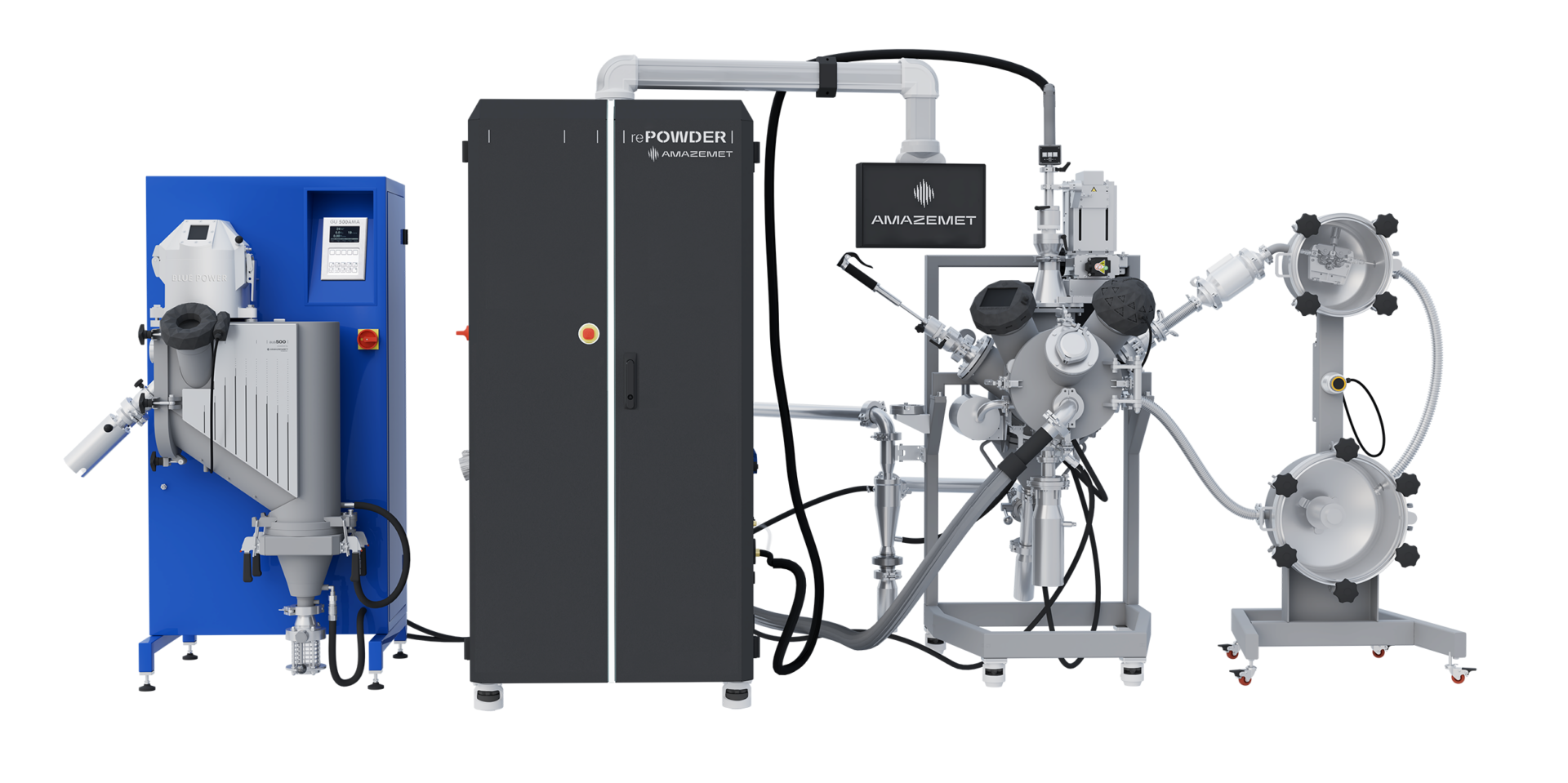
AMAZEMET positions itself around metal AM technologies, tailored powder manufacturing, R&D support, and engineering services. The company also states that it has worked with more than 200 alloys and offers custom metal powders as well as services that include metal 3D printing and CNC machining for demanding small and medium production runs. That makes AMAZEMET especially relevant for projects where the challenge is not just “make a metal sample,” but “develop a functional prototype for a demanding geometry or material case.”
It is equally important to set expectations correctly. If a reader is looking for every possible metal prototyping route, including broad-volume sheet metal or conventional mass manufacturing services, that is a wider field than AMAZEMET’s core specialization. But for companies developing advanced parts through https://www.amazemet.com/”>metal additive manufacturing, custom powders, and R&D-driven prototype work, that specialization is exactly the point.
Conclusion: metal prototyping should follow design intent, not process limitations
The biggest risk in prototype development is not failure. It is false validation. If a part is simplified so heavily for machining that it no longer represents the true design, the prototype may create confidence without delivering real insight.
That is why complex geometry changes the rules. For accessible, conventional shapes, machining remains highly effective. But when internal passages, lightweight structures, consolidated functions, or performance-driven forms are central to the design, AM offers a better path from CAD to meaningful test part.
For engineers working on advanced metal prototypes, the real question is not whether additive manufacturing is fashionable. It is whether traditional methods are forcing compromises that the project can no longer afford.
Share this content!